Introduction
An artificial hand is one that replaces a missing part of the human hand. Prostheses are the artificial replacement for missing human limbs.Throughout history, we can see evidence of people using some sort of devices that helped them to do the tasks much more easily, wood, metal, and other materials were used at first, then lighter materials were being used and then the process evolved to make the devices much more human body like. Nowadays we can see advanced prosthetics that are so much similar to human limbs and mimic the functions as well, but the cost involved is high and since these designs are under the protection of patents there are very less chances of people using them especially in developing or underdeveloped countries, although many open sources crowdfunded companies have come up that help people with their disabilities there is a lot of work to be done to make it affordable.
Problem definition
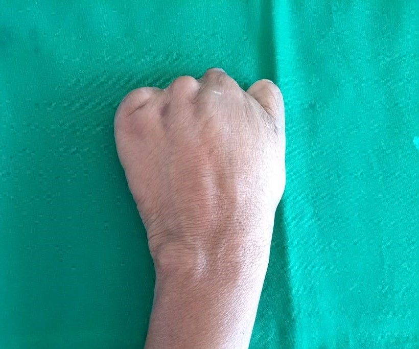
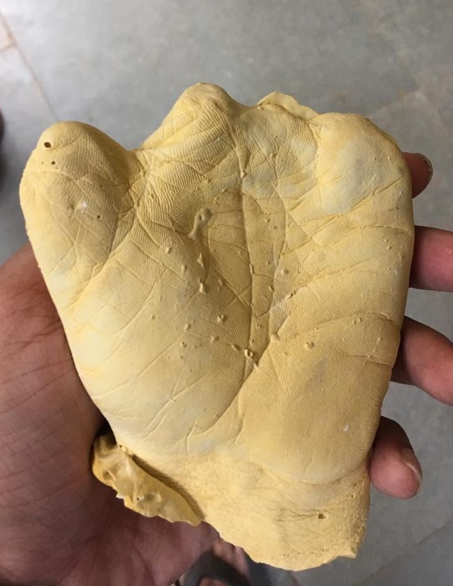
Our problem statement is how we might design, and make available to amputees with a palm but no fingers, prosthetic fingers that adapt instantaneously to the movement of the thumb. The pictures of the amputed hand of the patient is shown below.
| Amputed Hand (Back view) | Mould of the same hand (Front view) |
|---|---|
 |  |
Design Process
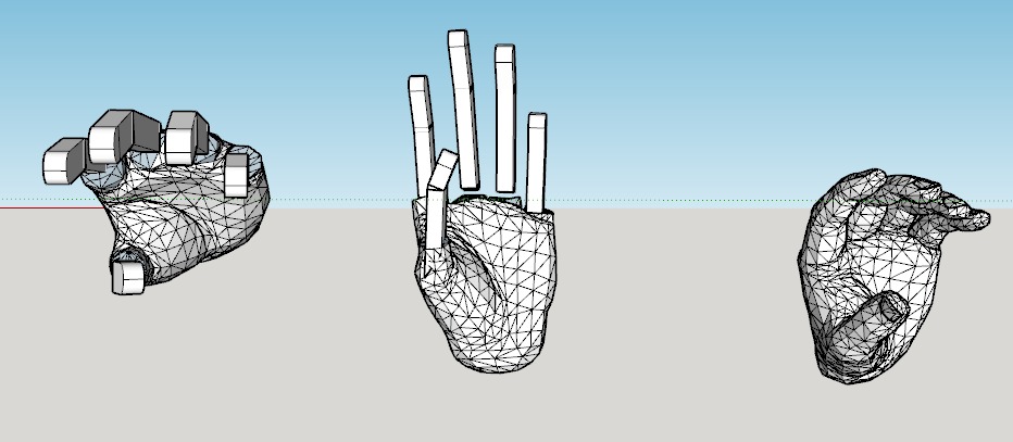
We had to first get a digital model to design our attachment, this was done by 3D scanning the moulds. The aim was to design fingers and an attachment that exactly fit the contours of the amputed hand so as to retain maximum movement of the hand, the project was done with the help of prostodontists and with their consultation the following approach was decided. One concept image is shown above, we were experimenting and looking at the way we could design the fingers and the movement mechanisms such that it exactly matched with the other hand. The image below shows how we scanned the moulds to get the digital copy with which we could further design the attachment.
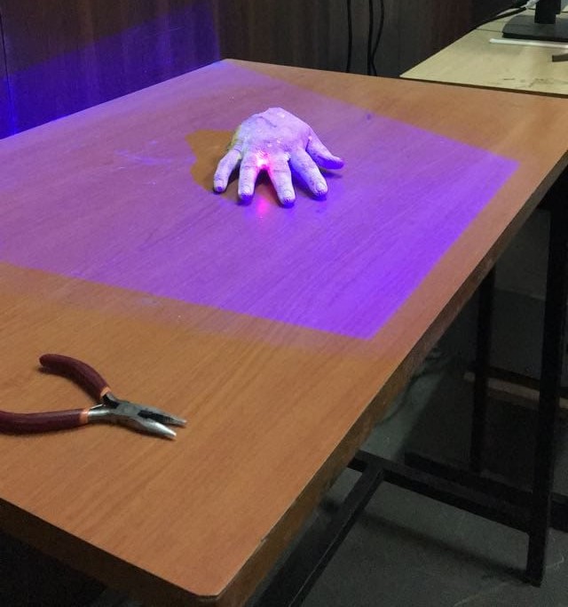
The 3D scans of both hands(Right and left) are shown below.
| Left Hand | Right hand |
|---|---|
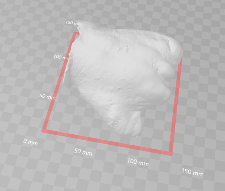 | 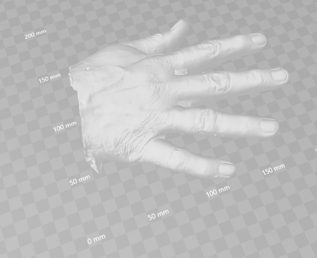 |
These scans were done by a 3D scanner, the size of the scans were huge since it was captured in the highest possible resolution, this needed to be reduced for further processing and an opensource software was used to perform simplification and reduce the size.
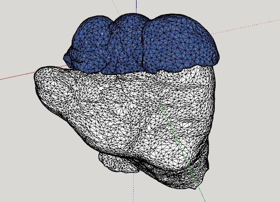
In order to design an attachment that exactly fit the countours, the best idea was to directly take a portion of the scans and scale it such that it is an exact carbon copy of the hand, this required a couble of tries however it was achieved by using some extensions within Sketchup. I also would like to add that we had done an analysis as to which software to use to do the editing and design, while Catia is very much trused by the industry, obtaining a liscense and the required extensions for 3D printing design was difficult and hence we went with an unusual choice of Sketchup. Sketchup allowed us to visualize the scans which were in the .stl format and maniplate and work with the scans in an intuitive manner. After reducing the size of the .stl files and importing them in Sketchup it was further easy to edit and manipulate the files, some pictures of the scans are shown below.
| Left Hand back | Left hand front |
|---|---|
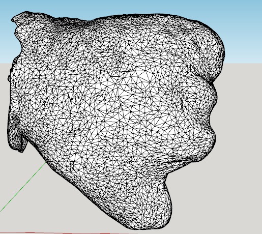 | 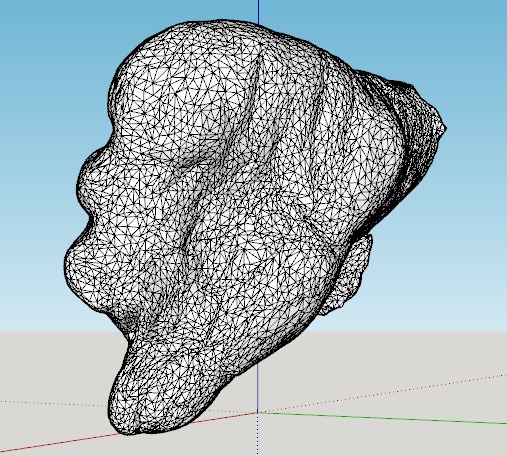 |
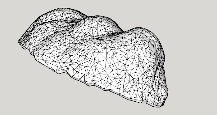
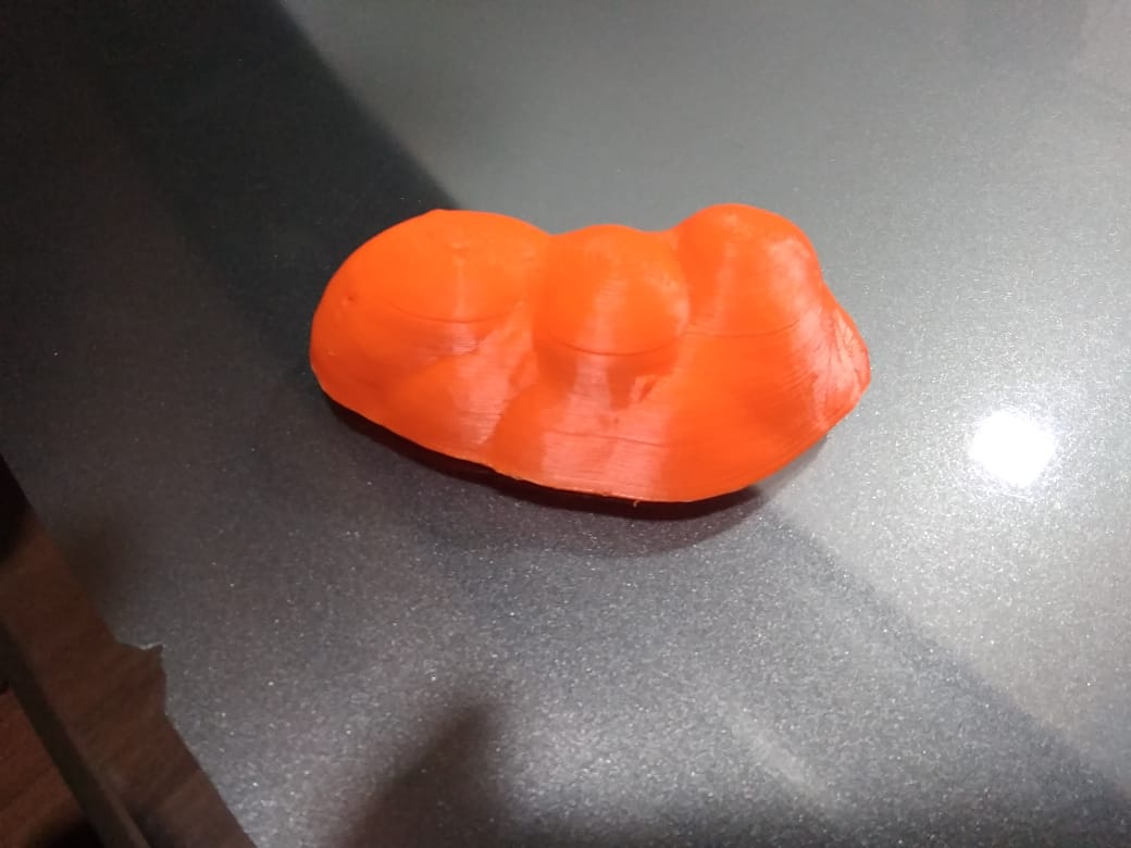
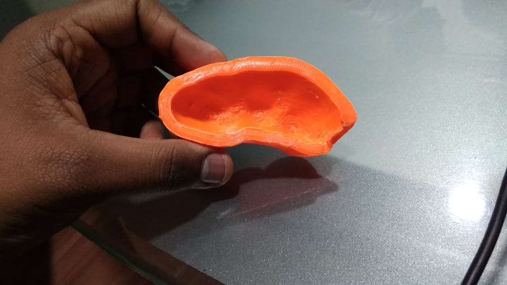
The front part of the scans wes cut and some thickness was provided, this then had to go through multiple cleaning processes in order to be sent to a slicer and 3D printed, the process of cleaning the files will be explained in a section below, the edited files and the 3D prints are shown below.
| Attachment | Prints |
|---|---|
 |  |
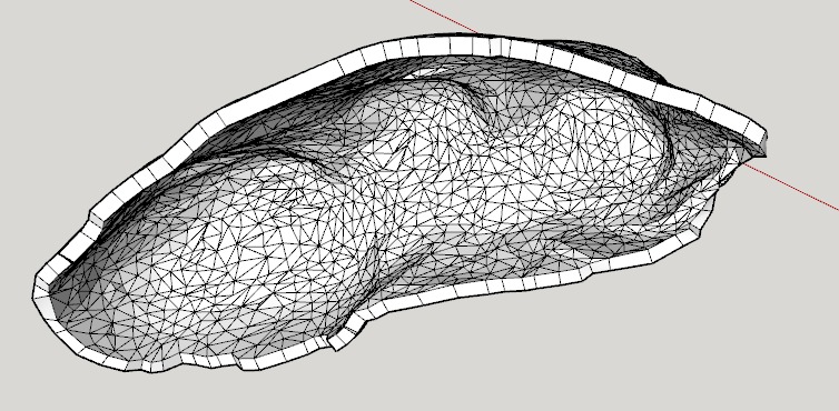 |  |
The attachment was check in the 3D environment wheter it would fit the hands of the patient, the image shown below shows that enough clearances were provided for the attachment to slide over the amputated hand.
Softwares and Processes
The softwares used to process and edit the files are listed below,
- MeshLab
- MeshMixer
- Netfabb online tool
- SketchUp
The functions of the softwares are described below.
Meshlab
MeshLab is a 3D mesh processing software system that is oriented to the management and processing of unstructured large meshes and provides a set of tools for editing, cleaning, healing, inspecting, rendering, and converting these kinds of meshes. MeshLab is free and open-source software, subject to the requirements of the GNU General Public License (GPL), version 2 or later, and is used as both a complete package and a library powering other software. It is well known in the more technical fields of 3D development and data handling.
The automatic mesh cleaning filters include removal of duplicated, unreferenced vertices, non-manifold edges, vertices, and null faces. Remeshing tools support high-quality simplification based on quadric error measure, various kinds of subdivision surfaces, and two surface reconstruction algorithms from point clouds based on the ball-pivoting technique and on the Poisson surface reconstruction approach. For the removal of noise, usually present in acquired surfaces, MeshLab supports various kinds of smoothing filters and tools for curvature analysis and visualization.
MeshMixer
MeshMixer is a tool made by Autodesk used to modify and work with meshes, it is a part of a suite of free applications developed by Autodesk to work with 3D models and meshes.
Netfabb online tool
The Netfabb Online Service is an easy-to-use solution for anyone with access to an internet connection and a web browser to repair 3D model files.
Sketchup
Google SketchUp is the most intuitive way to design, document and communicate ideas in 3D form. SketchUp is a 3D modeling computer program which is used for a wide range of drawing applications. SketchUp removes many of the time-consuming frustrations of learning how to use the software. SketchUp is designed to be easy to use. To create a line, you simply drag with the mouse; the software automatically makes it straight and attaches it to other lines in the project. The simplicity of the software makes it extremely quick to take a sketch and recreate into any 3D object. SketchUp Free was released as a web-based application which replaces SketchUp Make. Drawings can be saved to the cloud, saved locally as native SKP file or exported as an STL file. We used this software to create and edit the designs for our attachment and fingers.
The design processes are listed below,
- Scanning
- Editing
- Repairing
- Printing
Scanning
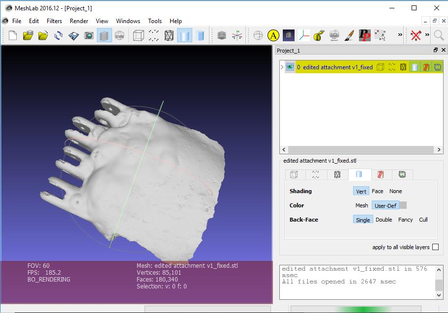
The mould of the amputated was taken and was scanned using a 3D scanner, this provided us with the detailed images of the hand, the contours and the bumps which were the part of the hand. The scans were repaired for imperfections and then exported in .stl format (stl means stereolithography). The scans were of high detail which was not necessary for the design of the attachment and hence the scans were subjected to another round of repair using another software called MeshLab. The mesh was imported in the software and the processes applied. This software has many functions which can be used to remove the details, the functions used were
a. Simplification: MC Edge collapse
b. Simplification: Quadratic Edge Collapse Decimation
The above functions reduce the complexity and decrease the size which is suitable for further editing. The edited mesh is then exported and saved with another name, this file is also in the .stl format and will be further used in the editing process.
| Meshlab Software | Meshlab Software with attachment |
|---|---|
 |  |
Editing
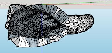
The editing of the scanned meshes is done in Sketchup. The mesh is imported, then it is exploded to highlight the individual triangles, then the unwanted parts of the scans are removed, the above process is shown in the images below.
| Attachment edited in sketchup | Thumb prosthetic in sketchup |
|---|---|
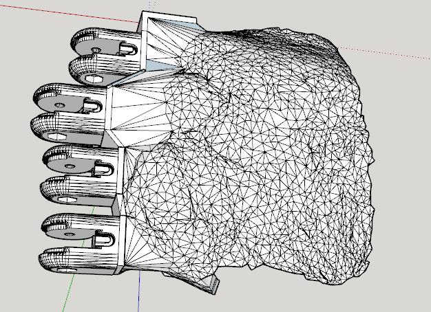 |  |
The next process is to provide thickness to the scans since they are just in a single layer. This is done using an extension in Sketchup called joint push-pull. The extension has special algorithms that intelligently provide thickness to complex shapes and automatically deletes the overlapping parts and fills in the empty parts to provide a smooth surface. This technique was used to create thickness in the attachment.
Next process was to add the hinges, this was again imported in the workspace and then places at the appropriate position in 3D space and then the required support was added. The joining of the hinges cannot be always successful since the meshes should be interweaved without any errors, this, however, can be fixed using another software and the process is explained below.
Repairing
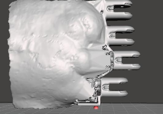
Since the edited meshes can have some problems during editing, it is absolutely necessary to have some repairing process so that the printer prints the files without any errors and the final product matches the exact design from the outside as well as inside. A software called MeshMixer is used to remove holes as well as imperfections from the design.
The mesh is imported in this software and then converted to solid, this shows the internal and external imperfections and then with the other tools we can fill in the holes and export the fixed mesh.
The process, however, does not stop here, another free service called Nettfab online tool is used to further automatically fix the files and to prepare them for printing, the mesh is uploaded and the fixed file downloaded and sent to printing.
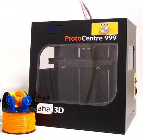
| Attachment during repair | 3D printer |
|---|---|
 |  |
Printing
The files were then processed using a slicer and then printed using a AHA 3D printer which is shown in the figure above.
Movement mechanism
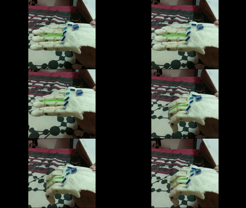
Now that the fingers were printed a movement mechanism had to be developed, this was achived by employing a technique based on the paper by [paper reference(will be added later)]. Artificial tendons made of plastic fibres were used , these were directly connected to the motor, the turing of the motor made these fibres to wrap up and reduce in length, this caused the closing movement of the fingers, the rotation in opposite direction reduced the tension and due to the force provided by the rubber bands attached on the joints, the fingers returned at their original position.
Conclusion
In conclusion, the goal of this project was to redesign prosthetic fingers to meet the need of an amputee who has lost her fingers. Following a multi-step design process, the team was able to
- Research and study the design of prosthetic hands so that we could base our design off it.
- Design an attachment that connects fingers and palm of any amputee according to their size.
- Developing a movement mechanism to perform basic tasks such as grasping.
- Achieve these objectives while keeping the cost low.
Attaching the final photo of the prosthetic worn by the patient.
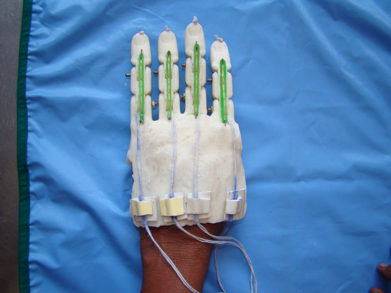
The gif showing the movement mechanism is as shown below.
Note: work in progress...Blog to be updated with more information
